Car Bus | Detailed Introduction of CAN
1¡¢ CAN Introduction
1.1 What is CAN?
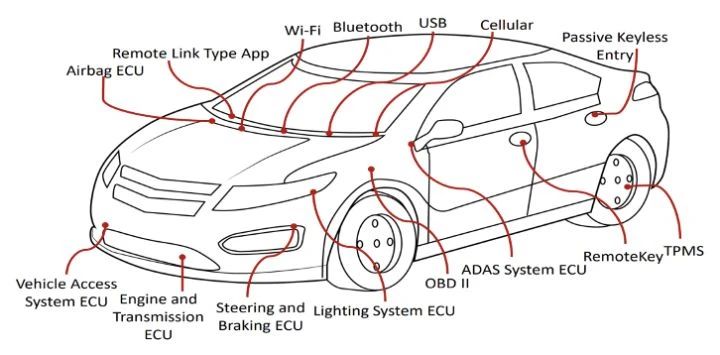
The CAN (Controller Area Network) bus protocol is a serial communication bus based on message broadcasting mode invented by BOSCH. It was initially used to achieve reliable communication between ECUs in automobiles, but due to its simplicity, practicality, and reliability, it has been widely used in other fields such as industrial automation, ships, and healthcare.

1.2 Development of CAN

In 1983, BOSCH launched an internal project to study an in car network.
In February 1986, at the Society of Automotive Engineers (SAE) conference, BOSCH announced the CAN bus protocol as a solution for automotive electronics.
In 1987, Intel and Philips introduced the first CAN controller chip.
In 1991, the Mercedes Benz 500E was the world's first mass-produced vehicle based on the CAN bus system.
In 1991, BOSCH released the CAN2.0 standard, which was divided into CAN2.0A (11 bit identifier) for standard format and CAN2.0B (29 bit identifier) for extended format.
In 1993, the ISO organization officially issued the CAN international standards ISO 11898 (high-speed applications, data transmission rate less than 1Mbps) and ISO 11519 (low-speed applications, data transmission rate less than 125Kbps)
1.3 Characteristics of CAN bus
It can work in a multi master manner, and any node on the network can actively send information to other nodes on the network at any time, regardless of master-slave, with flexible communication methods.
Data can be received through several transmission methods, including point-to-point, point to multipoint (group), and global broadcasting. Nodes on the network can be classified into different priorities to meet different real-time requirements.
Adopting a non-destructive bit arbitration bus structure mechanism, when two nodes simultaneously transmit information to the network, the node with lower priority actively stops data transmission, while the node with higher priority can continue to transmit data without being affected.
The maximum direct communication distance can reach 10km (speed below 4Kbps), and the maximum communication speed can reach 1MB/s (with a maximum distance of 40m)
The maximum number of nodes can reach 110
Adopting a short frame structure, the effective byte count for each frame is 8 bytes
Each frame of information has CRC verification and other error detection measures, resulting in an extremely low data error rate
Communication media can use twisted pair cables, coaxial cables, and optical fibers. Generally, inexpensive twisted pair cables are sufficient
The traditional station address encoding has been abolished and replaced with encoding of communication data blocks.
1) Theoretically, the number of nodes in the network can be unlimited
2) The identification of data blocks can be composed of 11 bit or 29 bit binary numbers, so 211 or 229 different data blocks can be defined
3) The data block encoding method allows different nodes to receive the same data simultaneously
In the event of a serious error, a node has the function of automatically shutting down the bus, cutting off its connection with the bus, so that other operations on the bus are not affected.
2¡¢ Key points of CAN bus
2.1 Application of CAN
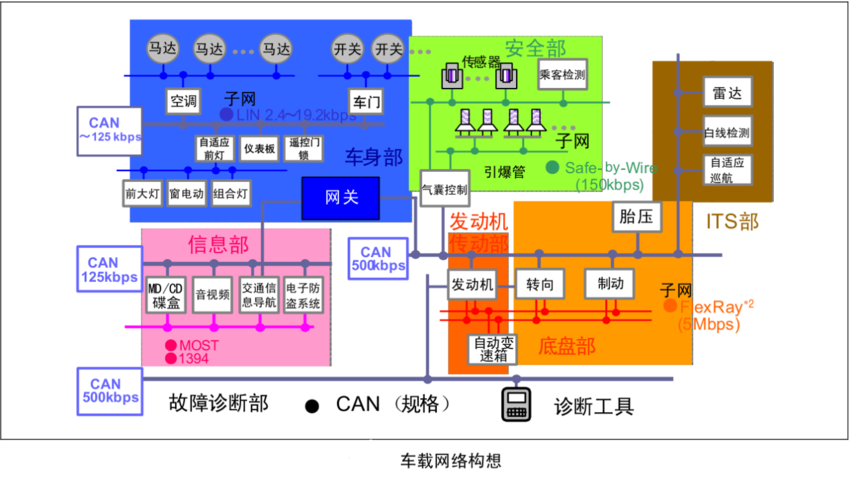
(1) Vehicle Network Concept
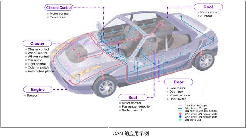
(2) Application examples
(3) Connection diagram
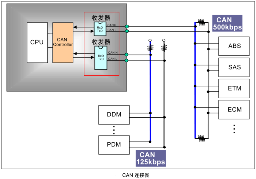
2.2 Basic Concepts of CAN Protocol
(1) ISO model and CAN protocol
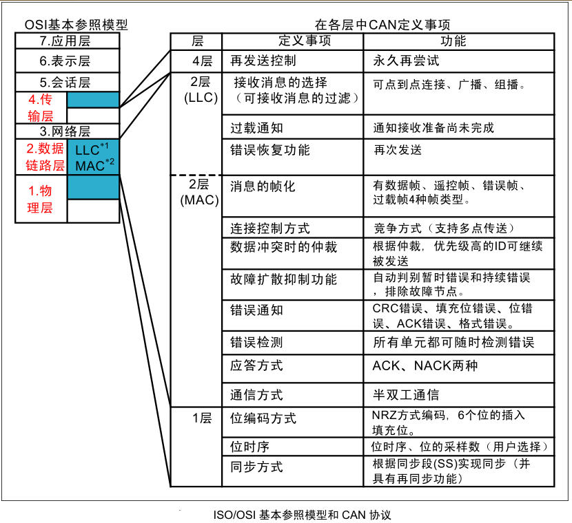
(2) Physical layer characteristics of ISO 11898 and ISO 11519-2

(3) The main differences between the physical layers of ISO 11898 and ISO 11519-2
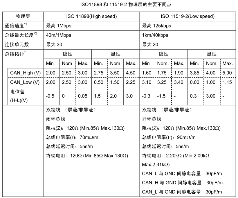
(4) Communication speed and maximum bus length

(5) CAN protocol and standard specifications
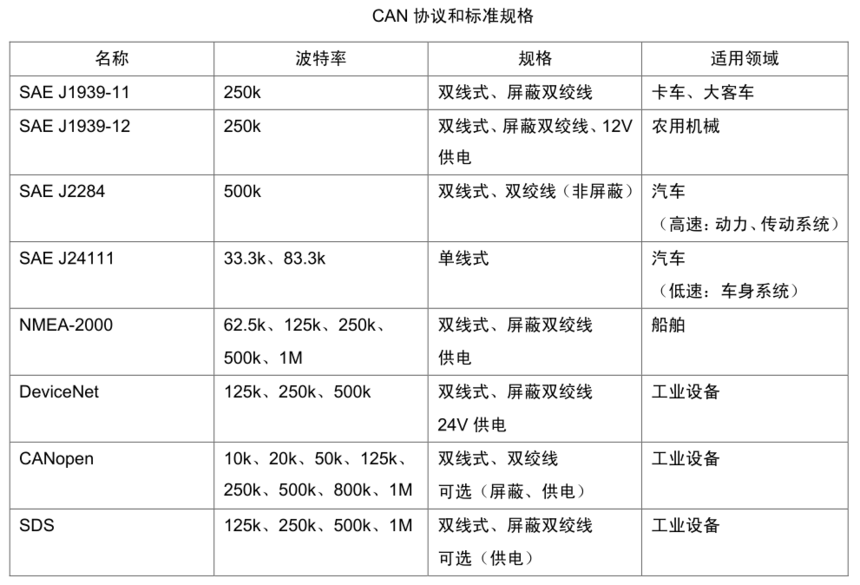
(6) Classification of communication protocols
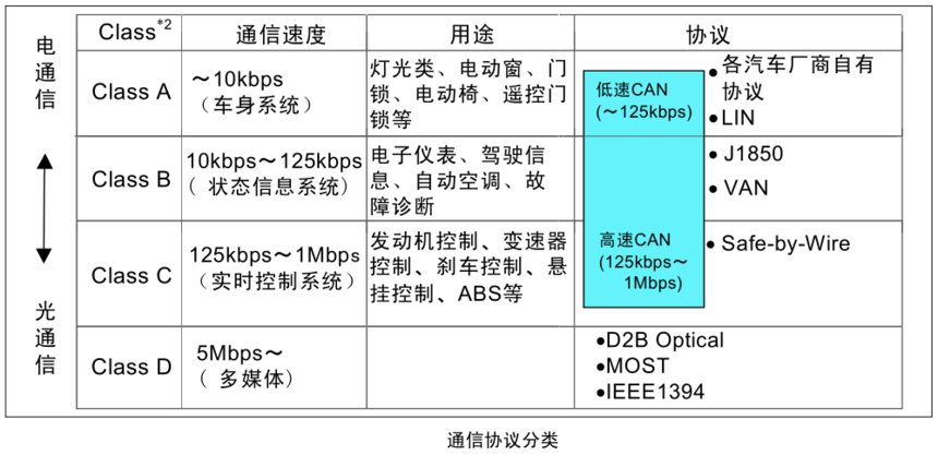
2.3 CAN protocol
Ö¡µÄÖÖÀ༰ÓÃ;

(1) Data frame
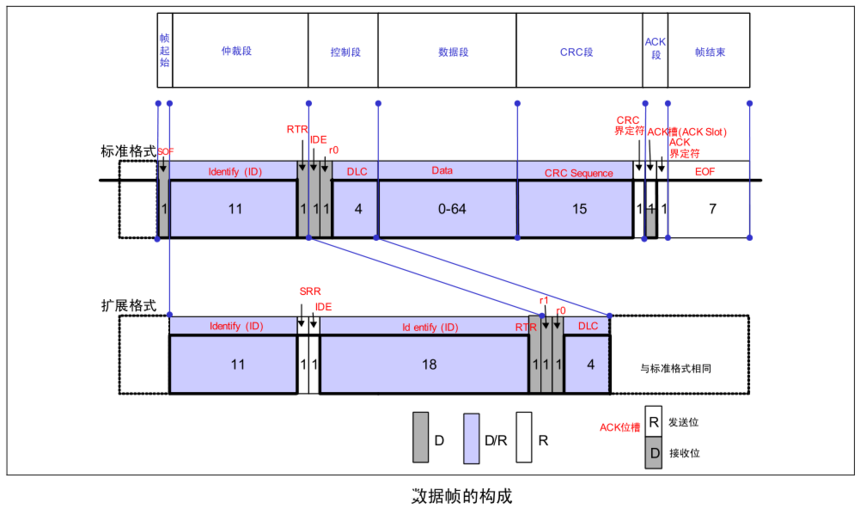
The data frame consists of 7 segments, namely:
¢Ù Frame Start: Refers to the segment where the data frame begins.
¢Ú Arbitration segment: a segment indicating the priority of the frame.
¢Û Control segment: a segment that represents the number of bytes and reserved bits of data.
¢Ü Data segment: The content of the data, which can send 0-8 bytes of data.
¢Ý CRC segment: The segment that checks for transmission errors in a frame.
¢Þ ACK segment: A segment indicating confirmation of normal reception.
¢ß Frame End: Refers to the segment where the data frame ends.
(2) Remote control frame
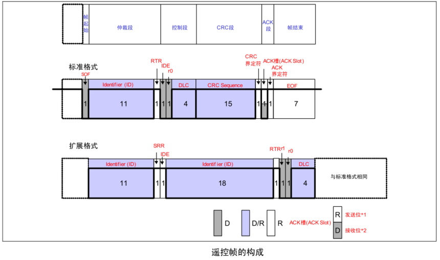
The remote control frame consists of 6 segments, namely:
¢Ù Frame Start (SOF): Refers to the segment at the beginning of the frame.
¢Ú Arbitration segment: a segment indicating the priority of the frame. Can request data frames with the same ID.
¢Û Control segment: a segment that represents the number of bytes and reserved bits of data.
¢Ü CRC segment: The segment that checks for transmission errors in a frame.
¢Ý ACK segment: A segment indicating confirmation of normal reception.
¢Þ Frame End: The segment indicating the end of the remote control frame.
(3) Error frame
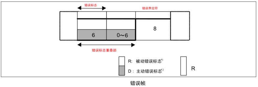
¢Ù Error flag
Error flags include two types: active error flags and passive error flags.
Active error flag: a 6-digit display bit.
Passive error flag: 6 hidden bits.
¢Ú Error delimiter
The error delimiter consists of 8 hidden bits
(4) Overload frame
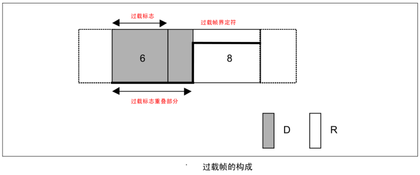
¢Ù Overload symbol
6 dominant positions
The composition of the overload flag is the same as that of the active error flag.
¢Ú Overload delimiter
8-bit implicit bit
The composition of overload delimiters is the same as that of error delimiters.
(5) Frame interval
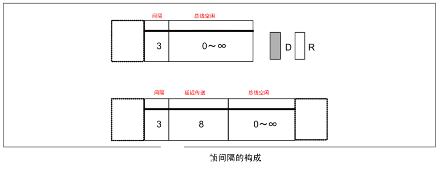
Frame interval is a frame used to separate data frames from remote control frames. The data frame and remote control frame can be separated from any previous frame (data frame, remote control frame, error frame, overload frame) by inserting frame intervals.
Frame intervals cannot be inserted before overload frames and error frames.
¢Ù Interval
3 hidden positions.
¢Ú Bus idle
Implicit level, no length limit (0 is also acceptable). In this state, it can be considered that the bus is idle, and the unit to be sent can start accessing the bus.
¢Û Delayed transmission (sending temporarily stopped)
The implicit position of 8 digits. The segment contained only in the frame interval immediately after the unit in passive error state sends a message.
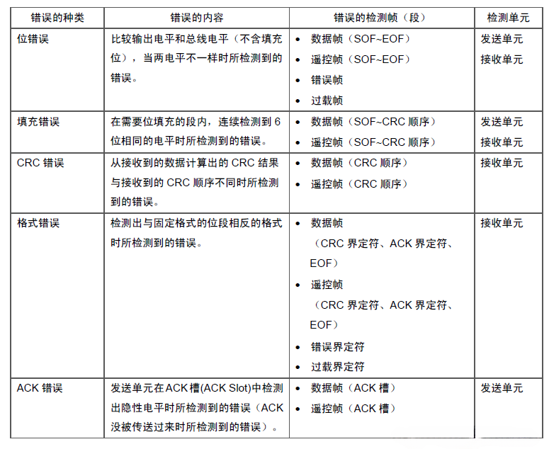
2.4 Types of Errors
There are 5 types of errors, and multiple errors may occur simultaneously.
Position error
Fill in error
CRC error
Format error
ACK error
3¡¢ Supplementary points
3.1 Signal transmission technology data
(1) CAN bus maximum propagation speed: 1Mbps
(2) ISO classification
Low speed type: less than 10kbps (used for rearview mirror adjustment, power windows, lighting, wipers, etc., called LIN bus)
Low speed type: 10-125kbps (used for comfort systems, instrument displays, etc.)
High speed type: 125kbps-1Mbps (used for engine control, ABS, transmission control, etc.)
(3) Maximum number of access control units: 32
(4) Universal version: Bosch CAN 2.0
3.2 Interference Issues
(1) Two data cables are wrapped around each other to prevent electromagnetic interference and outward radiation, with a specified twist distance of 20mm.
3.3 CAN transceiver interface
(1) Three commonly used interface devices
M12 small connector, OPEN5 connection terminal, DB9 socket
3.4 Explicit and Implicit Levels
There are two types of voltage levels on the bus: explicit and implicit.
When executing logic on the bus, the logical value of the explicit level is "0" and the implicit level is "1". 'Explicit' means' priority ', as long as a unit outputs an explicit level, it is the explicit level on the bus. Moreover, 'implicit' implies' inclusiveness', as only when all units output an implicit level, the bus is at an implicit level. (Explicit level is stronger than implicit level)
¡ª¡ªEND¡ª¡ª
推薦
-
-

QQ空間
-

新浪微博
-

人人網
-

豆瓣

