Car Bus | Detailed Introduction of CANFD


1. Main reason: With the increasing number and complexity of automotive functions, the load rate of traditional CAN bus (CAN2.0) is getting higher and even up to 95%.
2. Limitations of traditional CAN:
The maximum transmission rate is 1Mbit/s (typically ≤ 500Kbit/s), and the actual usage rate in the automotive field is up to 500Kbit/s, which cannot meet the increasing data throughput.
The additional overhead of traditional CAN data frames exceeding 50% (overhead>50%)
The effective data field of each frame message is 8 bytes, accounting for less than 50% of the entire frame message information
It is difficult to cope with the threats of new vehicle buses such as FlexRay and Ethernet in terms of performance.
3. Main features of CAN FD:
CAN FD leverages the advantages of CAN and compensates for its shortcomings.
Adopting the same event triggering mode as CAN communication, the software is easy to develop and port.
The maximum data transmission rate reaches 5Mbit/s, better meeting the requirements of high real-time and high data transmission rate applications
The effective data field of each frame message is 64 bytes, accounting for more than 70% of the entire frame message information
Compared to emerging buses such as FlexRay and Ethernet, the cost is lower.
4. Historical factors: It is impossible for automobiles to directly abandon the current traditional CAN bus technology. In order to solve the problem of CAN bus load rate while being compatible with CAN bus and not having too high research and development costs, the latest revised version of ISO 11898-1 (classical CAN and CAN FD) was released in 2015.
3、 Comparison between CAN FD and CAN bus
(1) The main differences between CAN and CAN FD are: different transmission rates, different data field lengths, different frame formats, and different ID lengths.
1. Variable rate: CAN FD adopts two bit rates, from the BRS bit in the control field to the ACK field (including CRC delimiter), which is the variable rate, and the rest is the rate used by the original CAN bus.
2. Increase in data field length: CAN FD has greatly expanded the length of the data field, with DLC supporting a maximum of 64 bytes. When DLC is less than or equal to 8 bytes, it remains the same as the original CAN bus. Due to non-linear growth when DLC is greater than 8 bytes, the maximum data field length can reach 64.

Compared to traditional CAN data frames, CAN FD adds EDL bits, BRS bits, and ESI bits to the control field, and adopts a new DLC encoding method and a new CRC algorithm (CRC field extended to 21 bits)
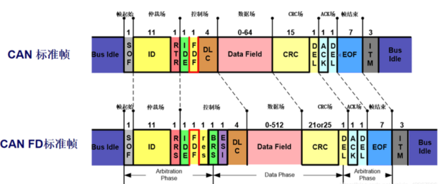
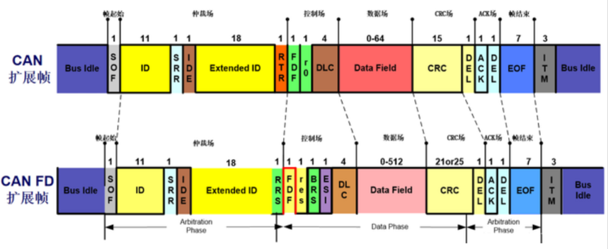
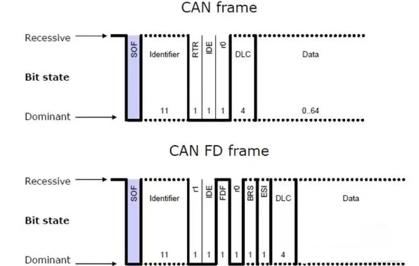
Frame start, the traditional CAN data frame start bit is the same as the CAN FD data frame start bit SOF, which is used to identify the start of a data frame and is an explicit bit. Nodes can only send SOF when the bus is idle.

The maximum length of CAN standard frame ID is 11 bits, and the length of CAN FD standard frame ID can be extended to 12 bits.


10. DATE Field Data Field
①CRC-stuff count

CAN FD has improved in terms of security. To avoid the impact of bit padding on CRC, CAN FD has added a stuff count in the CRC field to record the number of padding bits corresponding to the modulus of 8, represented by Grey Code, and also added parity check bits. FSB (fixed stuff bit) is fixed as the complement of the previous digit.


②CRC
With the expansion of the data field, in order to ensure the quality of information transmission. The CRC calculation of CAN FD should not only include the bits of the data segment, but also the Stuff Count and padding bits from SOF. By comparing the calculation results of CRC, it can be determined whether the receiving node can receive normally.
In CAN, the number of CRC bits is 15, while in CAN FD, the CRC field is extended to 21 bits.
When transmitting data of 16 bytes or less: CRC 17 bits
When transmitting data exceeding 16 bytes: CRC 21 bits
③ CRC delimiter
The CRC delimiter indicates the end of the CRC check field and is a 1-bit normal recessive bit. However, in CAN FD, considering the distance between nodes, a maximum of 2 bits of time are allowed at the receiving end. The data field (variable speed segment) of the CAN FD frame is the first sampling point of the CRC delimiter.
12. ACK response field
The ACK response field of CAN FD includes response gaps and response delimiters, which have the same composition as CAN. Differently, the length of the CAN response field is 1 bit, and the CAN FD receiving node recognizes it as a valid response using 2 bits of time.

Ensure that the message is correctly received by at least one node, the sending node sends the implicit bit, and the receiving node sends the explicit bit after receiving it correctly.
13. EOF(End of frame)
End identifier, indicating the end of the data frame. In CAN/CAN FD, the fixed format consists of 7 consecutive hidden bits' 1 '
(3) Differences between CAN FD and other frame formats
Advantages of CAN FD over Flexray:
① The development cost of CAN FD is much lower than that of Flexray;
② Flexray is not friendly to ECU upgrade flashing.
Advantages of CAN FD over Ethernet:
① The development cost of CAN FD is much lower than that of Ethernet;
② The advantage of Ethernet lies in the transmission of big data, but it is not fully applicable to current automotive architectures.
(4) Advantages of CAN FD
Communication efficiency and speed between multiple ECUs increased by 30 times
Downward compatible
Allow a single message to carry more data
Increase network bandwidth
Improve protocol efficiency
Reduce protocol loss
Flexible switching between faster and slower data rates
By utilizing advanced CRC, the number of undetected errors has been reduced
Simplified processing, more reliable
(5) Comparison of CAN FD and CAN Performance


推薦
-

-

QQ空間
-

新浪微博
-

人人網
-

豆瓣

