Car Bus | Detailed Introduction of FlexRay
foreword
The CAN, CAN FD, and LIN buses were introduced earlier, and this article introduces the FlexRay bus.
The corresponding articles are as follows:
CAN bus:Car Bus | Detailed Introduction of CAN
CAN FD bus:Car Bus | Detailed Introduction of CANFD
lin bus:Car Bus | LIN Detailed Introduction
Summary of commonly used vehicle buses:Car Bus | Understanding the Five Major Car Buses in One Text: CAN, LIN, FlexRay, MOST, Ethernet

1、 Introduction to FlexRay
What is FlexRay?

1.2 History of FlexRay Bus
In 2000, BMW and DaimlerChrysler joined forces with Philips and Motorola to establish the FlexRay Alliance. The alliance is committed to promoting the adoption of the FlexRay communication system globally, making it a standard protocol for advanced powertrains, chassis, and wire control systems.
Its specific tasks include defining FlexRay requirements, developing FlexRay protocols, defining data link layers, providing controllers that support FlexRay, developing FlexRay physical layer specifications, and implementing basic solutions.
Mainly used for wire controlled operations, such as wire controlled steering, anti lock braking system (ABS) including vehicle stability control (VSC) and vehicle stability assistant (VSA), etc.
The FlexRay Alliance released the ISO 17458 standard specification in 2013.
The first mass-produced car using FlexRay was launched in the BMW X5 in 2006 and applied in the electronic control shock absorption system.

1.3 Characteristics of FlexRay
FlexRay offers a plethora of features that traditional in car communication protocols do not possess, including the following six aspects:
1. High transmission rate: Each channel of FlexRay has a bandwidth of 10Mbps. It can not only operate as a single channel system like CAN and LIN networks, but also as a dual channel system, thus achieving a maximum transmission rate of 20Mbps, which is 20 times the current maximum operating rate of CAN;
2. Synchronous Time Base: The access method used in FlexRay is based on synchronous time base. The time base is automatically established and synchronized through a protocol, and provided to the application. The accuracy of the time base is between 0.5 μ s and 10 μ s (usually 1-2 μ s);
3. Certainty: Communication is carried out in a continuous cycle, and specific messages have a fixed position during the communication cycle, so the receiver already knows the arrival time of the message in advance. The temporary deviation in arrival time will be very small and can be guaranteed;
4. High error tolerance: Powerful error detection performance and fault tolerance are important aspects considered in the design of FlexRay. The FlexRay bus uses cyclic redundancy check (CRC) to detect errors in communication. The FlexRay bus provides redundant functionality through dual channel communication, and the use of star topology can completely solve fault tolerance problems;
5. Flexibility: In the development process of the FlexRay protocol, the main focus is on flexibility, which is reflected in the following aspects:
▶ Support multiple network topology structures;
▶ Message length configurable: The corresponding data payload length can be set according to the actual control application requirements;
▶ When using a dual channel topology, it can be used to increase bandwidth and also to transmit redundant messages;
▶ The time for static and dynamic message transmission during the cycle can vary depending on the specific application.
6. Reliability: In order to operate reliably in automotive environments, FlexRay meets the following requirements:
▶ It can meet the temperature environment requirements for automotive use, with the current standard being -40~125 ℃. For some special applications, such as brake actuators, the temperature requirements are even higher;
▶ Without the use of external filters, each FlexRay product meets the EMC requirements of automotive systems and regulations;
▶ In normal operation and low-power mode, the system power consumption must be optimized to the minimum.
In idle state, the typical operating current of the bus driver and communication controller is 10mA;
In busy mode, the typical operating current of the bus driver and communication controller is 50mA;
The bus driver current when turned off (referring to the current consumed by the bus driver monitor wake-up logic after the car voltage regulator is turned off) is 10 μ A;
▶ The conditions for adapting the power supply voltage of the communication controller are consistent with the requirements of the automotive ECU (Electronic Control Unit);
▶ The input/output of the bus controller and communication controller directly connected to the wiring harness meets the requirements of the automotive electrical system.
2、 Introduction to FlexRay Protocol
2.1 Basic structure of nodes
(1) There are three basic types of nodes in the FlexRay network, namely synchronization nodes, cold start nodes, and application task nodes.
① Synchronization nodes provide support for clock synchronization algorithms in the network to achieve synchronization functionality.
② The characteristic of a cold start node is that it can send a start frame before the network is synchronized, supporting the initialization process of communication between the node and the network. The cold start node must be a synchronization node.
③ In addition to these two types of nodes, there are also some nodes in the network that complete certain application functions, which are application task nodes.
(2) Basic composition and interface information of nodes
The basic structure of a node generally consists of five parts: microcontroller, communication controller, bus management logic, bus driver logic (send/receive driver), and power system.
The communication function mainly consists of a communication controller, bus management and driver logic, as well as the interface between these parts and the host.

The information interface relationship between various parts of the node is shown in the figure.

2.2 Basic Functions of Nodes
(1) In a node, a communication controller is connected to one or two bus drivers, meaning that a node can be connected to one or two bus channels;
(2) Nodes can enter sleep mode;
(3) Nodes in sleep mode can be awakened by bus events;
(4) The bus activity of nodes can be turned off by the main controller;
(5) The node is always connected to the power supply;
(6) The application function of the node.
A network star node is a node that only has network functions, without a main controller or communication controller. A star node has more than one bus driver, which can be awakened by the bus and shut down by the bus.
2.3 FlexRay Physical Structure
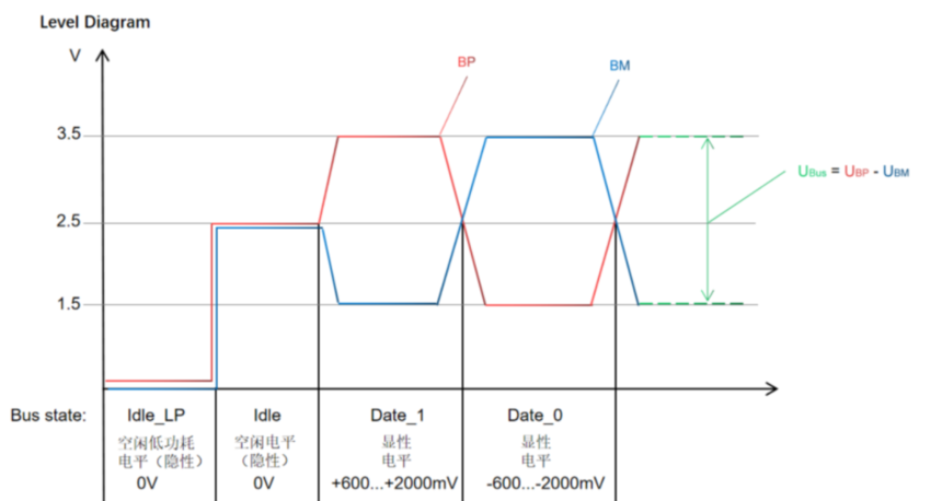
The FlexRay bus, like CAN, is also composed of two wires, which can be shielded or unshielded twisted pair cables. Each channel has two wires, namely Bus Plus (BP) and Bus Minus (BM). Encode using Non Return to Zero (NRZ) method.
The bus status can be determined by measuring the voltage difference between BP and BM, which can reduce the impact of external interference on bus information, as interference can cancel each other out when acting on two wires simultaneously.
Each channel requires a terminal resistor of 80-110 ohms. Loading different voltages on two wires of a channel can cause the bus to have four states: Idle_Lp (Low power), Idle, Data_0, and Data_1
Explicit: The differential voltage is not 0V (Data-0 and Data_1);
Implicit: The differential voltage is 0V (Idle_Lp, Idle). In a stationary state, the two bus transmission lines have a high ohmic value of approximately 2.5V.
2.4 FlexRay topology structure
The topology structure of FlexRay is divided into three categories: line type (point-to-point, multi node), star type, and hybrid type.
(1) Bus topology structure
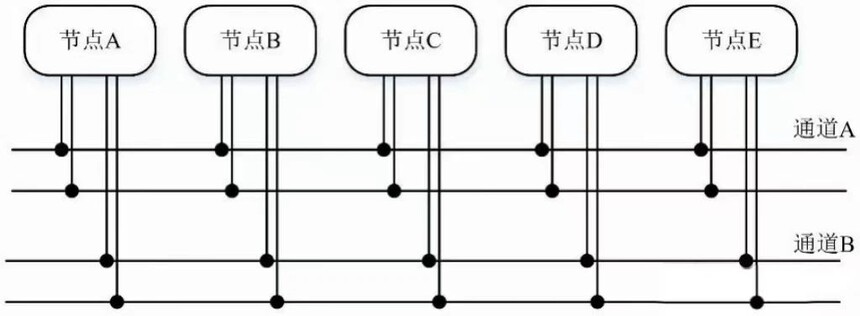
The FlexRay network has a dual bus topology structure, where each node can be connected to two buses or only one bus.

(2) Star shaped structure
The star topology structure of FlexRay network has multiple connection methods.
① A dual channel single star structure, where each channel is connected by a star node, and a node can be connected to one or two channels (star nodes).

② A structure in which two single channel star shaped structures are cascaded, each channel is connected by a star node, and one node is connected to one channel (on the star node), with the two star nodes interconnected.

③ On the basis of the star shaped dual channel topology of the FlexRay network, redundant channel structures can also be constructed.

④ Advantages of star shaped structure
It provides a point-to-point connection between the receiver and transmitter. This advantage is particularly evident in high transmission rates and long transmission lines.
Another important advantage is the error separation function. For example, if two lines used for signal transmission are short circuited, the bus system cannot communicate further on that channel.
(3) Hybrid structure of bus type and star type
In addition to using bus and star structures, FlexRay networks can also use a hybrid network topology as long as each cascaded subnet does not exceed the limit of the number of nodes.
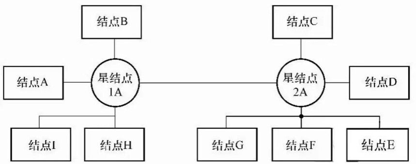
As shown in the above figure, a star node (2A) is directly connected to a node and connected to a bus, which in turn is connected to some other nodes; Then it is connected to another star node (1A), which directly connects some nodes and can also be connected to the bus.

A dual channel structure consisting of a star topology and a bus type structure.
2.5 Redundant Data Transmission
In fault-tolerant systems, even if a bus wire breaks, it is necessary to ensure that data can continue to be transmitted reliably. This requirement can be achieved through redundant data transmission on the second data channel. A bus system with redundant data transmission capability uses two independent channels. Each channel is composed of a set of double wire conductors. When a channel fails, the information that should be transmitted on that channel can be transmitted on another channel that has not experienced the failure.
2.6 FlexRay transmission process
(1) The FlexRay network organizes the transmission of information in a cyclic manner. When transmitting information, a communication cycle has two parts: static and dynamic. The dynamic and static segments are composed of several time slices, with each time slice transmitting a FlexRay frame. FlexRay frames are formatted bitstreams.
(2) The current communication cycle is identified by the value of the communication cycle counter, which is an up only counter that counts the communication cycle. The configuration data of the communication controller determines the length of the communication cycle, which can be set by the application program. The communication controller can only start a communication cycle when the bus is in the allowed state. The information content of a node can be sent multiple times at specific time slots in different communication cycles. The transmission methods of static and dynamic information are different.
① FlexRay communication cycle
A communication cycle of FlexRay includes static segments, dynamic segments, symbol windows, and network idle time vectors.


② The basic execution process of communication cycle
In addition to the startup phase, the FlexRay communication cycle is executed periodically with a fixed number of macro clocks. The communication cycle is counted sequentially from 0 to a maximum value that can be set. Bus arbitration is based on frame identifiers in both static and dynamic segments. The frame identifier determines which segment of the communication cycle it is sent in and which time slot of that segment.

③ Static segment


⑤ Symbol Window
A FlexRay communication cycle can have one symbol window. The symbol window is configured to set a certain number of macro clocks with a time width of zero, indicating that the symbol window is not needed. The content and functionality within the symbol window are specified by high-level protocols, and FlexRay nodes send a symbol representing a custom special purpose.
Symbol category:
Conflict avoidance symbol: used for communication startup of cold start nodes
Test symbol II: used for bus testing
III wake-up symbol: used for initializing the wake-up process
⑥ Network idle vector
The idle vector of a FlexRay communication cycle is an indispensable part for adjusting the FlexRay network. After deducting the time used in the first few segments of a cycle, the remaining length is the idle segment. A communication cycle can dynamically configure the bandwidth of dynamic segments and network idle vectors according to the actual needs of nodes. Within the idle vector time range of the network, nodes in the FlexRay network do not engage in any communication.
(3) Due to the fact that the static and dynamic parts of a FlexRay communication cycle can be empty, there are three forms of a communication cycle: pure static (with an empty dynamic part), static dynamic hybrid (with both static and dynamic parts), and pure dynamic (with an empty static part).
① The static part of FlexRay has the following characteristics:
The static part of a communication cycle can be programmed with its number of time slices;
Within a communication cycle, a node can be programmed to set the time slots it can use;
The static part allows at most one node to send one frame of information to the channel in each time slot, and the static part of the communication cycle accesses the media in TDMA mode;
The length of static time slices is the same and can be set by the program;
The communication start symbol is before the first time slot of a communication cycle.
② The dynamic part of FlexRay has the following characteristics:
There may be no or several dynamic time slots within a communication cycle;
During a communication cycle, the static part has priority access to the bus;
In the dynamic part of the communication cycle, the Mini Plotting Scheme and identifier priority arbitration strategy are adopted, where nodes with higher identifier priority receive arbitration for the transmitted information;
The information length of the dynamic part is variable during network operation.
3、 FlexRay frame structure

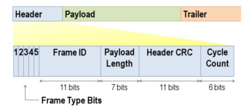
1) The starting segment is 5 bytes long (40 bits), including: status bit (5 bits), frame ID (11 bits), effective data segment/payload length (7 bits), header CRC (11 bits), and loop count (6 bits).

The effective data segment contains the actual data transmitted in the frame. The maximum length of a valid data frame in FlexRay is 127 words (254 bytes), which is 30 times longer than CAN.

The end segment of the frame contains three 8-bit CRCs used for error detection. The CRC check code is calculated from the start segment and the payload segment. When calculating the CRC, it is placed in the CRC generator from the reserved bit to the last bit of the effective data segment according to the network transmission order for calculation.
3.4 Encoding and decoding of frame bitstream
An information frame needs to be encoded for transmission at the physical layer. Encode the information to be transmitted in a frame, along with location identification and synchronization requirements, into a binary bit stream. Each frame is sent out by the sending node in the physical layer as a set of bit streams; The receiving end decodes these bitstreams, decomposes them into a frame of information, and provides it to the link layer.
The encoding process is actually the corresponding "packaging" processing of the data to be sent, such as adding various check bits, IDs, etc.
Note: Encoding and decoding mainly occur between the communication controller and the bus driver

(1) Encoding insertion sequence
Encoding insertion sequence is a binary sequence added to a frame during encoding, which includes the following types:
① Transmission Start Sequence (TSS): used to initialize the docking of nodes and network communication, consisting of a small segment of low level. When the sending node starts sending, it first outputs a continuous low bit sequence, whose length can be configured to indicate the start of transmission and establish a path between the sending and receiving ends. When the receiving end node detects this state, it determines that the bus has entered a busy state from idle, and the transmission process of one frame begins.
② Frame Start Sequence (FSS): A high bit added after TSS to compensate for quantization errors in TSS partial synchronization.
③ Byte Start Sequence (BSS): provides data timing information to the receiving node, consisting of one high level and one low level. BSS consists of consecutive high and low bits. The sending node adds BSS before each byte of information (every 8-bit data) in a frame to provide time synchronization information to the receiving end.
④ Frame End Sequence (FES): After all the information in a frame is sent, the sending node immediately sends one low and one high sequence, indicating the end of the frame.
⑤ Dynamic Trailing Sequence (DTS): Used for the frame tail of dynamic segments, indicating the accurate time of the micro time slice working point at the sender. DTS consists of two parts: low first and then high. The low part can be variable in length and maintain at least one bit time. At the working point of the next micro time slice, it becomes higher, while the high part is fixed as one bit time. The sending node sends DTS immediately after FES when sending frames of dynamic segments.
(2) Static frame encoding and dynamic frame encoding
① Divide all information in a frame into bytes;
② Add a TSS at the beginning of the bitstream;
③ Add FSS after TSS;
④ Insert BSS before each byte of frame data to obtain extended bytes;
⑤ Arrange all extension bytes in the order of the original frame information data;
⑥ Calculate the CRC checksum of the frame and add each byte of the checksum to BSS for byte extension;
⑦ Add an FES after the bitstream formed as above;
⑧ If it is a dynamic segment frame, add a DTS after it.


Encoding of dynamic segment frames


5、 Equipment recommendation

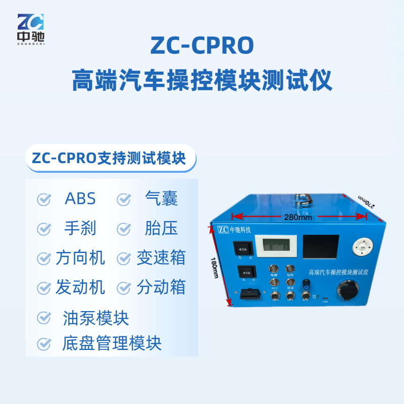
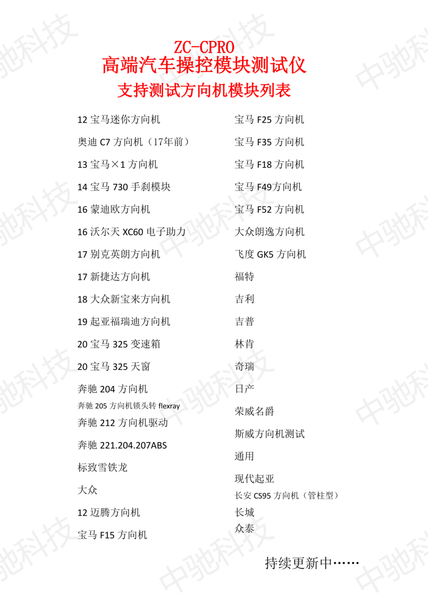
ZC-CPRO supports testing modules
ZC-CPRO支持测试列表





推薦
-

-

QQ空間
-

新浪微博
-

人人網
-

豆瓣

