Components | One article takes you through the concept of "inductance" in components
Electronic components are a general term for components and devices.
Electronic components: such as resistors, capacitors, inductors, etc. that do not generate electrons themselves and have no control or conversion effect on voltage and current, known as "passive devices"
Electronic devices: such as transistors, diodes, field-effect transistors, integrated circuits, etc., which can generate electrons themselves and have control and conversion effects on voltage and current, known as "active devices"
Zhongchi will explain electronic components in stages for everyone. In this issue, let's learn about inductors together.
INDUCTOR

1、 Types of inductors
1. Classify by appearance
(1) Hollow inductor (hollow coil)
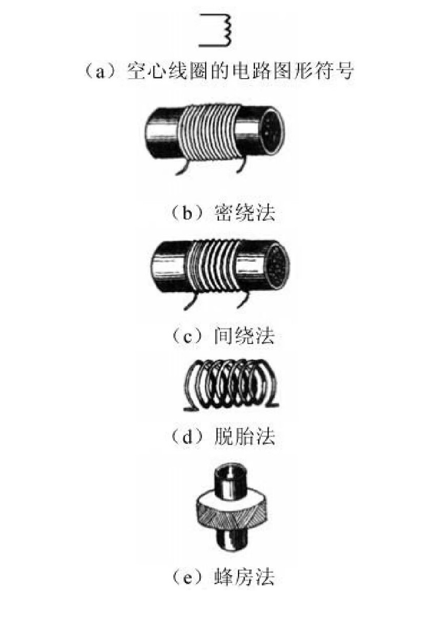
① Hollow coil is a type of coil formed by winding wires around paper, rubber, or plastic tubes, or by spin off after winding. As there is no additional dielectric material in the middle of such coils, they are called hollow coils. There are various methods for winding hollow coils, such as dense winding, indirect winding, emerging winding, and peak room winding.

(2) Magnetic core inductor (coil wound on magnetic core)
① Magnetic core coils are coils made by winding wires around magnetic cores or rings, or by inserting magnetic cores into hollow coils, all of which are called magnetic core coils.


③ Magnetic rod coil
A magnetic rod coil is an inductive component in which a coil is wound around a magnetic rod. This greatly increases the inductance of the coil.

④ Magnetic ring coil
The basic structure of a magnetic ring coil is to wind a coil around a ferrite magnetic ring.

2. Classify by job nature
Inductors can be classified into high-frequency inductors (various antenna coils, oscillating coils) and low-frequency inductors (various chokes, filtering coils, etc.) according to their working properties.
(1) Oscillating coil
The oscillating coil is one of the main components in wireless receiving equipment, consisting of a magnetic core, a magnetic cover (magnetic cap), a plastic skeleton, and a metal shielding cover. The coil is wound around the plastic skeleton (or magnetic core), and the magnetic core or magnetic cap can be adjusted to change the inductance of the coil within ± 10%. Widely used in amplitude modulation, frequency modulation radios, television receivers and other equipment.
(2) Choke coil
① A choke coil, also known as a choke coil, choke coil, or differential mode inductor, is a coil used to restrict the passage of alternating current. It is divided into high-frequency choke coils and low-frequency choke coils. Adopting an open magnetic circuit design, it has the characteristics of excellent structure, small size, high Q value, and low cost.

② Function of choke coil: By utilizing the proportional relationship between coil reactance and frequency, it can suppress high-frequency AC current and allow low-frequency and DC to pass through. According to the frequency, air cores, ferrite cores, silicon steel sheet cores, etc. are used.
③ When used for rectification, it is called a "filtering choke coil"; When used to suppress audio current, it is called an "audio choke coil"; When used to suppress high-frequency currents, it is called a "high-frequency choke coil". The inductance coil used for "passing DC and blocking AC" is called a low-frequency choke coil, and the inductance coil used for "passing low-frequency and blocking high-frequency" is called a high-frequency choke coil.
④ Choke coils are mainly used in laptops, inkjet printers, display monitors, mobile phones, broadband data machines, game consoles, color televisions, cameras, microwave ovens, lighting equipment, automotive electronic products, etc.
3. Classified by packaging form
Inductors can be classified into ordinary inductors, color ring inductors, epoxy resin inductors, surface mount inductors, etc. according to their packaging forms.
(1) Surface mounted inductor
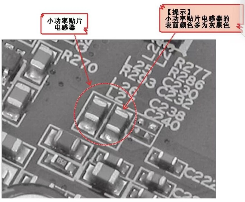
① Low power chip inductor
The external volume of low-power chip inductors is similar to that of ordinary chip resistors, and the surface color is mostly gray black.
② High power surface mount inductor

4. Classified by inductance
Inductors can be classified into fixed inductors and adjustable inductors based on their inductance.
(1) Fixed color ring inductor
① Fixed color ring inductor is a small fixed inductor with a fixed inductance. It is a coil with a magnetic core that is wound on a soft magnetic ferrite substrate, encapsulated with epoxy resin or plastic, and labeled with a color ring on its outer shell to indicate the value of inductance.

② Features:
Sturdy structure, low cost, suitable for automated production.
Special iron core material, high Q value and self resonant frequency.
The outer layer is treated with epoxy resin for high reliability.
The inductance range is large and can be automatically plugged in.
(2) Fixed color code inductor
Fixed color code inductors are small fixed inductors that use color dots to indicate the numerical value of inductance.
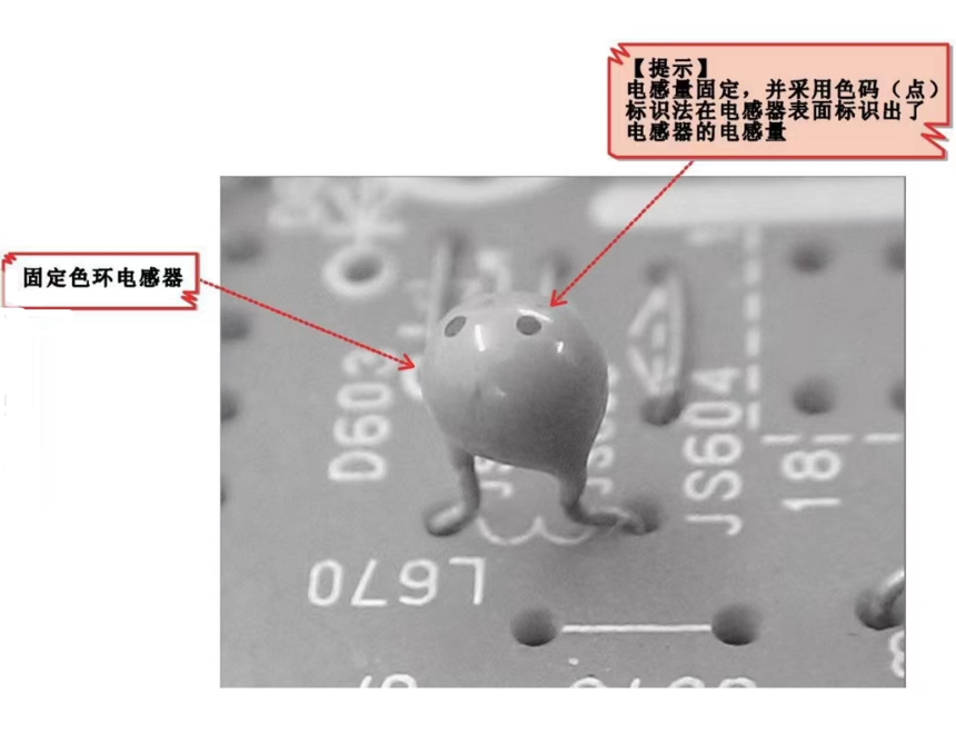
Fixed color code inductors are compact in size and have relatively stable performance. They are widely used in electronic devices such as televisions and recorders for filtering, trapping, choke, and delay line circuits.
(3) Fine tune the inductor
Fine tuning an inductor refers to an inductor that can adjust its inductance, and its circuit symbol is induction-13.png. Fine tuned inductors are generally equipped with a shielding shell and a strip-shaped slot on the magnetic core for adjustment.

2、 Identify commonly used inductors
Direct labeling method
(1) The direct labeling method is to identify the resistance value and other parameters of an inductor on the inductor through some code symbols. The direct labeling method for inductors usually adopts a simplified approach, which means only important information is identified, rather than all being labeled.


① Product Name: Represented by letters, such as inductor represented by L.

② Inductance: The amount of inductance indicated on the surface of an inductor, represented by a mixture of letters and numbers.
③ Allowable deviation: represented by letters, indicating the maximum allowable deviation range between the actual inductance and the nominal inductance of the inductor.

Example:
The inductance of the "5L713G" inductor above is 713 μ H, where "L" represents the inductor; 713G "represents inductance; G "acts as a decimal point because it follows the number" 713 ", resulting in an inductance of" 713 μ H "for this inductor.

In the standard definition of fully digital annotation format:
① Significant digit 1: The first significant digit of the inductance value.
② Significant digit 2: The second significant digit of the inductance value.
③ Multiplier: Refers to the number of zeros after a significant number.
For example, 0 represents 100, 1 represents 101, 2 represents 102, 3 represents 103, and 4 represents
104……
The default unit is "Weiheng" (μ H).
Example:

The inductor in the above figure is labeled as "101". According to regulations, the first two digits represent the effective value of the inductance, which is "10", and the third digit "1" represents "101". Therefore, the inductance of this inductor is 10X101=100 μ H.
② Number+letter+number annotation format

① Significant digit 1: The first significant digit of the inductance value.
③ Decimal point: The middle letter serves as a decimal point.
③ Significant digit 3: The first significant digit of the inductance value.
Example:

The inductor is named "3R3", and the first and third digits of this labeling method are the effective values of the inductance, with the middle R serving as a decimal point. Therefore, the inductance of the inductor is 3.3 μ H.
2. Color code method
The color marking method for inductors can be divided into color ring marking method and color code marking method.
① Color ring marking method


① The first significant digit of the nominal value.
② The second significant digit of the nominal value.
③ The number of zeros after the nominal value (multiplier).
④ Allowable deviation.
Note: The above four parameters are represented by color rings of different colors, where each color represents a different multiplier.

Color Ring Identification Method Color Corresponding Meaning Table
Example: For example, the color rings on the surface of an inductor are in the order of "brown, orange, gold, and silver". Brown represents the significant number 1, orange represents the significant number 3, and gold represents the multiplier factor 10-1; Silver indicates an allowable error of ± 10%. Therefore, the inductance of the inductor is 13 × 10-1=1.3 μ H ± 10%.
② Color code marking method

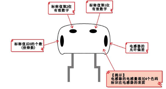
① The first significant digit of the nominal value.
② The second significant digit of the nominal value.
③ The number of zeros after the nominal value (multiplier).
④ Allowable deviation.
Note: The above four parameters are represented by color dots of different colors, which represent
Different numerical values.


By comparing the colors of each dot in the color coded inductor in the figure with the corresponding meanings in the color coded identification method, it can be seen that the first significant digit of the inductor is "2" and the second significant digit is "5"; The multiplier is "100", and the allowable error is ± 10%. Therefore, the nominal inductance of this inductor is 25X100=25 μ H, and the allowable error is ± 10%
3、 Understand the main parameters of commonly used inductors
1. Unit of inductor
The wire is wound into a circular shape to form an inductor, and the more turns it is wound, the greater the inductance. The unit of inductance is Henry, abbreviated as Hen, represented by the letter "H". Millihenries (mH) and microhenries (μ H) are more commonly used as units, and their relationship is 1 H=103mH=106 μ H.
2. Main parameters of inductance
The main parameters of capacitors include nominal capacity (capacitance), allowable deviation, rated operating voltage, insulation resistance, temperature coefficient, and frequency characteristics.
(1) Inductance
Inductance is a physical quantity that measures the ability of a coil to generate electromagnetic induction. When a current is applied to a coil, a magnetic field will be generated around the coil, and magnetic flux will pass through the coil. The larger the current passing through the coil, the stronger the magnetic field and the greater the magnetic flux passing through the coil. The magnetic flux passing through the coil is proportional to the current flowing in, and their ratio is called the self inductance coefficient, also known as the inductance. The magnitude of inductance is mainly determined by the diameter, number of turns, and presence or absence of iron core of the coil, namely:

L - inductance
Φ -- Magnetic flux through the coil
I - Current
(2) Allowable error
The maximum allowable deviation range of the actual inductance of an inductor relative to its nominal value is called the allowable error
(3) Sensory Resistance XL
The magnitude of the resistance of an inductive coil to AC current is called reactance XL, measured in ohms. Its relationship with inductance L and AC frequency f is XL=2 π fL.
(4) Quality factor Q of the coil:
It is a physical quantity used to measure the quality of a coil, represented by the letter "Q". The higher the Q value, the lower the power consumption and efficiency of the inductor coil, indicating better "quality".
The Q value is related to the structure of the coil (wire thickness, multiple or single strands, winding method, magnetic core).
The ratio of the inductive impedance XL to its equivalent resistance, i.e. Q=XL/R. The higher the Q value of the coil, the smaller the loss of the circuit. The Q value of the coil is related to factors such as the DC resistance of the wire, the dielectric loss of the skeleton, the loss caused by the shielding cover or iron core, and the influence of high-frequency skin effect. The Q value of the coil is usually several tens to one hundred.
(5) Nominal current
The size of current allowed to pass through a coil is often represented by the letters A, B, C, D, and E, with nominal currents of 50, 150, 300, 700, and 1600 milliamps, respectively. The large volume of electric inductance, nominal current, and inductance are indicated on the casing.
(6) Distributed capacitance
The capacitance that exists between turns of a distributed capacitance (parasitic capacitance) coil, between the coil and the shielding cover, and between the coil and the base plate is called distributed capacitance. The existence of distributed capacitance reduces the Q value of the coil and deteriorates its stability, so the smaller the distributed capacitance of the coil, the better.
4、 Common detection methods for inductors
1. Detection method for inductive coils
Remove the inductor coil to be tested, adjust the range of the pointer multimeter to "RX10", and perform zero calibration.


Under normal circumstances, the resistance value of an inductor coil is around 1. If the detected resistance value is infinite, it indicates that the inductor may be damaged.

According to the color ring label on the color ring inductor, the inductance of the color ring inductor can be read. The color ring is arranged from left to right as "brown", "black", "brown", and "silver". The inductance of the color ring can be read as 100 μ H, with an allowable deviation of ± 10%.
According to the color code label on the color code inductor, the inductance of the color code inductor can be read. As can be seen, the first color code is gray; The second color code is blue; The third color code is brown. Based on the knowledge learned earlier, it can be recognized that the inductance of the color ring inductor is 860 μ H.
Adjust the range of the digital multimeter to 2mH and install a tester.

Detect the current inductance of the color ring

Under normal circumstances, the inductance obtained by detecting the color ring inductance is "0.114mH". According to the unit conversion formula 0.114mH × 103=114 μ H, it is basically consistent with the nominal value of the color ring inductance. If the measured inductance differs significantly from the nominal value, the inductor may be damaged.
3. Detection method for color code inductance

According to the color code label on the color code inductor, the inductance of the color code inductor can be read. The first color code is gray; The second color code is blue; The third color code is brown. It can be recognized that the inductance of the color ring inductor is 860 μ H.

Detect the current color code inductance


推薦
-

-

QQ空間
-

新浪微博
-

人人網
-

豆瓣

