Components | One article takes you through the "transistor" components

1、 Understand the transistor
1.1 Understanding of commonly used transistors
(1) Meaning
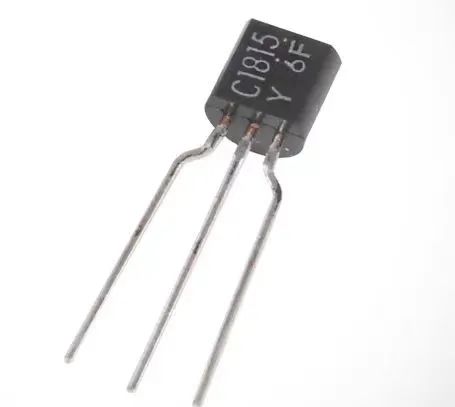
The full name of a transistor is "crystal transistor" or "transistor". It is a typical semiconductor component.
The three poles of a transistor:
Base (b): used to activate transistors
Collector (c): The positive electrode of a transistor (collecting charge carriers)
Emitter (e): the negative electrode of a transistor (emitting charge carriers)
The magnitude of the base current controls the magnitude of the current between the collector and emitter.
(2) Types
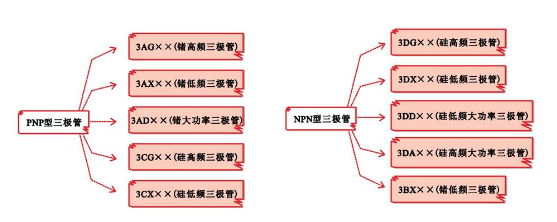
① The common transistors can be mainly divided into two categories based on their polarity structure: NPN type and PNP type.

PNP transistor: composed of two series connected crystal diodes.
NPN transistor: Basically used to amplify weak signals into strong signals.
② According to different power levels, transistors can be divided into low power, medium power, and high power.
Low-power transistor

Low power transistors have a power Pc generally less than 0.3W and are one of the most commonly used semiconductor devices in electronic circuits. It is generally used to amplify AC and DC signals or applied in circuits such as oscillators and converters. For example, used to amplify audio and video signals.

The power Pc of a medium power transistor is generally between 0.3W-1W, mainly used in driving circuits and excitation circuits, or to provide driving signals for high-power amplifiers.

The power Pc of high-power transistors is generally above 1W. Due to their high power dissipation, high-power transistors are prone to causing high temperatures inside the chip during operation. Therefore, it is usually necessary to install heat sinks to ensure proper heat dissipation. The larger the output power of a high-power transistor, the larger its volume, and the larger the required heat sink area for installation.

High-frequency transistor
The characteristic frequency fT of high-frequency transistors is greater than 3MHz and is commonly used in high-frequency amplification circuits, mixing circuits, or high-frequency oscillation circuits.

④ According to the different forms of plastic packaging, transistors are divided into patch packaging type, metal packaging type, and plastic packaging type.


Typically, triodes are named using the direct labeling method, but the specific naming specifications vary depending on the country, region, and manufacturer.
(1) Naming and labeling methods for domestically produced transistors
The naming specification for domestically produced transistors is to label the category, material, specifications, and other key parameters of the transistor on its surface.

Product Name: Represented by the number "3", indicating the effective polarity pin
Material/polarity: Use letters to represent the material and polarity of the transistor


Serial number: Use numbers to represent different varieties of similar products, used to distinguish the product's external dimensions and performance indicators.
Specification number: indicates the specification and model of the transistor production
Common domestic transistor models:

2.1 Three working states of the transistor
The working state of a transistor can be divided into cutoff state, amplification state, and saturation state.
(1) Deadline status
When the emitter junction of a transistor is reverse biased and the collector junction is reverse biased, the transistor will enter a cutoff state.

In the cut-off state, there is no conduction between the collector and emitter, which is equivalent to the faucet switch being tightly closed and the water flow in the faucet not coming out.
(2) Magnify state
When the emitter junction of a transistor is positively biased and the collector junction is negatively biased, the transistor will enter an amplifying state.

When the transistor is in an amplifying state, the current at the base increases slightly, and the current at the collector also increases accordingly. At this point, the magnitude of the base current ic of the transistor is proportional to the base current ib, where ic=β ib, where β is the DC current amplification factor representing the amplification capability of the transistor. Analogous to a controlled faucet, the water flow from the faucet is controlled by a switch (base), and if the switch is turned larger, the amount of water flowing out (collector) will also be slightly larger.

The magnitude of the saturation state transistor base current ic is not controlled by the base current ib, and there is a disproportionate relationship between ic and IB.
2.2 Three types of wiring for transistors
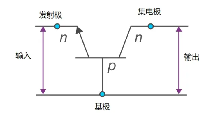
There are three types of transistor wiring: common base (CB), common collector (CC), and common emitter (CE).
(1) Transistor common base type
In a common base (CB) configuration, the base terminal of the transistor is common between the input and output.

(2) Transistor common collector type (CC)
In a common electrode (CC) configuration, the collector terminal is common between the input and output terminals.

(3) Common emitter type (CE) of transistor
In a common emitter (CE) configuration, the emitter terminal value is shared between the input and output terminals.

3.1 Structure and Composition
Diode: composed of a P-type semiconductor and an N-type semiconductor, forming a PN junction with only 2 pins, connecting the P-type and N-type semiconductors respectively.
Transistor: Composed of three layers of semiconductor materials, there are two structural types: NPN and PNP, with three pins: emitter, base, and collector.
3.2 Working principle
Diode: It mainly works by utilizing the unidirectional conductivity property of PN junction. Under forward bias (positive electrode connected to P-type semiconductor, negative electrode connected to N-type semiconductor), the diode conducts; Under reverse bias, the diode is turned off.
Transistor: controls the current between the emitter and collector (collector current) by adjusting the current between the base and emitter (base current). A transistor can amplify signals, meaning that a small base current can control a large collector current.
3.3 Application Fields
Diode: widely used in rectification, detection, voltage regulation, signal modulation and other circuits.
Transistor: mainly used in signal amplification, switching, modulation, oscillation and other circuits.
3.4 Functions and Special Effects
Diode: It has good unidirectional conductivity and can be used for unidirectional conduction of current.
Transistor: It not only has a switching function, but also amplifies signals, and is a very important component in analog and digital circuits.
Diode: Key parameters include forward voltage drop, reverse leakage current, maximum forward current, reverse recovery time, etc.
Transistor: Key parameters include amplification factor (β value), maximum collector current, breakdown voltage, switching speed, etc.

推薦
-

-

QQ空間
-

新浪微博
-

人人網
-

豆瓣

